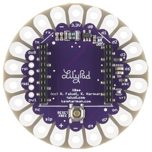
The LilyPad XBee is a radio transceiver that you can sew on to your clothing to create wireless wearables. It was created by Kate Hartman and Rob Faludi. It has been commercialized by Sparkfun Electronics as an addition to Leah Buechley’s extensive line of wired LilyPad clothing components.
SETUP
There are two ways you can attach your XBee radio to the Lilypad XBee:
- With female headers: This is how the board ships, and is a great setup for prototyping. You can easily swap out your radios to work with different models and antenna types.
- Soldered directly to the board: This is for projects that are more in their final stages, where you know you won’t be swapping your radios. This secures the radio to the board and reduces the profile of your board tremendously, making it nice and slim so it lies nicely in your clothes! With the current version of the board, you’ll need to desolder and remove the female headers.
Pin layout is similar but not the same as the pin layout on the XBee. Certain pins have been swapped to make sewing easier in projects that use the LilyPad Arduino, which has a different pin arrangement from the XBee.
Counter-clockwise from the top. Descriptions are for the 802.15.4 XBee and XBee Pro, but other versions are similar:
| Label | Description | XBee Pin |
| 3.3V | connect regulated power only, nominally limited to 3.4 Volts | 1 |
| — | ground | 10 |
| rx | data in | 2 |
| tx | data out | 3 |
| d08 | digital output 8 (not supported yet) | 4 |
| rst | reset | 5 |
| rssi | received signal strength indicator / PWM output 0 | 6 |
| pw1 | PWM (pulse-width modulation) output 1 | 7 |
| nc | no connection | 8 |
| slp | Sleep / digital input 8 / DTR | 9 |
| + | connect unregulated Voltage here | |
| — | ground (alternate connection) | 10 |
| d4 | analog input 4 / digital input/output 4 | 11 |
| d7 | digital input/output 7 / CTS | 12 |
| on | ON light output | 13 |
| vrf | Voltage Reference for analog / digital inputs | 14 |
| asc | association light output / analog input 5 / digital i/o 5 | 15 |
| d6 | analog input 6 / digital i/o 6 / RTS | 16 |
| d3 | analog input 3 / digital i/o 3 | 17 |
| d2 | analog input 2 / digital i/o 2 | 18 |
| d1 | analog input 1 / digital i/o 1 | 19 |
| d0 | analog input 0 / digital i/o 0 | 20 |
POWER SOURCES
LilyPad AAA step up connected to the + and — pins
Lithium Ion coin cells connected to the 3.3V and — pins (#2450 or larger recommended)
Lithium Ion battery packs connected to the 3.3V and — pins (larger size)
Common questions about the Board
What is a solder jumper?
Solder jumpers are really just a blob of solder that connects two pads together, completing a circuit. They form a semi-permanent connection, but can be removed with a simple soldering iron and a bit of solder wick. Later, they can be replaced to re-form the connection. This cycle can be performed repeatedly, though ideally not very often because eventually it will weaken the board. There are two solder jumpers on the LilyPad XBee board. One is by the d1 pad that completes a circuit for the LED lights and another by the vref pad that routes the supply current to the Voltage reference pin.
Why do lights have solder jumpers?
Sometimes you don’t want blinking lights on your board. Removing the upper solder jumper, by the d1 pin will disable both the ON and RSSI LED light.
Why does VRef pin have a solder jumper?
The Voltage reference pin tells the XBee what Voltage to set as the maximum level when reading an analog sensor. In most cases this will be the same as the XBee’ supply voltage so the jumper can be left in place. However, if you are using a different voltage for an analog sensor, then this jumper can be removed and that different voltage can be routed to the VRef pin.
